

-
AboutHebei Linaier Rubber Products Co., Ltd. is located in Duqiao Industrial Zone, Jingxian City, Hebei Province, adjacent to Dezhou, Shandong. Founded in early 2001 with a registered capital of 35 million yuan, it is a scientific

-
ProductMain products: vertical and horizontal imported and domestic filter plates, diaphragm plates, diaphragms and accessories; pinch valve sleeves and pinch valves and various mining accessories.
-
NewsIn 2013, our company's high-pressure cylinder with phenolic cloth support and guide ring obtained the national key new product certificate, project number: 2013GRA20011; its products in coal cylinders and engineering hydrauli
-
ServiceWe will actively cooperate with more enthusiasm, strengthen internal management, expand the market externally, improve various performance indicators of existing products, and truly achieve our win-win situation!
-
RecruitmentOur company always adheres to the talent concept of "people-oriented", provides a growth platform for talents, and realizes the common growth and development of enterprises and talents.


 Esperanto
 Shqiptare
 Euskara
 Zulu
 Latinus
 Cymraeg
 தமிழ்
 Slovak
 Slovak
 Afrikaans

What is a plate pressure filter and how does it work?
Release time:
2026-11-20
Author:
Linaier
Article overview
This guide covers the full technical and commercial picture of the plate pressure filter: working principle, type comparison, performance benchmarks, selection methodology, maintenance protocols, and EU compliance requirements. Targeted at process and procurement engineers operating in Finland and the broader Nordic market.
Table of contents
- 1. What is a plate pressure filter?
- 2. How does a plate pressure filter work? Step-by-step process
- 3. Main types of plate pressure filters and their differences
- 4. Key performance data: What numbers actually matter?
- 5. How to select the right plate pressure filter for your process
- 6. Maintenance, troubleshooting, and spare parts
- 7. Compliance and safety standards in 2026
- 8. Frequently asked questions
What is a plate pressure filter?
A plate pressure filter is a batch-operated solid-liquid separation device in which a series of filter plates are pressed together under hydraulic force to form sealed filter chambers, allowing pressurised slurry to be dewatered into a dry filter cake. It is one of the most widely deployed forms of pressure filtration equipment across mining, wastewater treatment, food processing, and chemical manufacturing.
At its most fundamental level, the equipment works by forcing a slurry — a mixture of solid particles suspended in liquid — through a permeable filter cloth media. The solids accumulate on the cloth surface as a filter cake, while the clarified filtrate drains away. This mechanism is what engineers classify as cake filtration, distinguishing it from depth filtration or membrane separation technologies.
Why do so many industrial operators rely on this technology? The answer lies in its combination of high throughput, low residual moisture in the cake, and adaptability to chemically aggressive or abrasive slurries. In Finland's mining sector alone, Tukes reported a total extraction volume of approximately 120.8 million tonnes in 2024 — a scale of operation that demands robust, high-capacity solid-liquid separation equipment capable of handling coarse mineral tailings as well as fine concentrate slurries.
It is worth noting from the outset that the term "plate pressure filter" can describe several distinct equipment architectures, from the classic plate and frame filter press to the more advanced recessed chamber filter press and hydraulic press filter designs. Each has a different operating envelope, and confusing them during the specification stage is a common and costly mistake.
How does a plate pressure filter work? Step-by-step process
The operating cycle of a plate pressure filter follows a repeatable batch sequence. Understanding each phase is essential before evaluating performance claims or comparing equipment offers.
The core filtration cycle explained
- Plate closing: A hydraulic ram compresses the stack of filter plates and frames together, forming a row of sealed filter chambers between adjacent plates. The hydraulic closing force typically ranges from 500 kN to over 15,000 kN depending on filter size.
- Slurry feed: A feed pump — often a progressive cavity or diaphragm pump — delivers the slurry under pressure (usually 4–16 bar) through the central feed port and into each filter chamber simultaneously.
- Cake formation: As pressure builds, liquid is forced through the filter cloth media and exits via the filtrate ports. Solid particles are retained on the cloth and begin building up as a filter cake. This phase continues until the chambers are full or the feed pressure reaches a preset maximum.
- Cake washing (optional): Wash liquid is introduced to displace residual mother liquor from the cake. This step is critical in pharmaceutical, food-grade, and certain hydrometallurgical applications.
- Air blow / membrane squeeze: In membrane filter press variants, inflatable rubber diaphragms on the plate faces are pressurised with compressed air or water (up to 16 bar) to mechanically squeeze the cake and further reduce moisture. Even without membranes, a compressed air blow-through step achieves partial drying.
- Plate opening and cake discharge: The hydraulic ram retracts, plates separate, and the filter cake falls — by gravity or mechanical vibration — into a discharge conveyor or hopper below.
- Cloth washing: Automated spray bars flush the filter cloth to prevent blinding and restore permeability before the next cycle begins.
What happens inside the filter chamber?
Think of the filter chamber as a kind of pressure sandwich. The filter cloth acts as a selective barrier — just as a coffee filter allows water through while holding back grounds — except operating at pressures that would be unrecognisable in a domestic kitchen. The driving force is the pressure differential across the cake: the higher the differential, the faster the filtrate flows. However, as the cake thickens, its resistance increases and flow rate naturally declines. This is why experienced process engineers monitor differential pressure curves, not just feed pressure, to judge when a cycle is genuinely complete versus merely slow.

The entire operating cycle — from plate closing to cake discharge — typically takes between 20 and 90 minutes depending on slurry characteristics, cake thickness target, and whether washing or membrane squeezing steps are included. For the filter press mechanism in its standard configuration, cycle times at the lower end of this range are achievable with well-conditioned, coarse-particle slurries.
Main types of plate pressure filters and their differences
Not all plate pressure filters are equal. Selecting the wrong configuration can lead to inadequate cake dryness, excessive cloth wear, or a throughput bottleneck that undermines the entire process line. Here is a clear breakdown of the main architectures in use in 2026.
Plate and frame filter press
The original and simplest configuration. Alternating flat plates and open frames are stacked together; the frames create the volume for cake accumulation. This design suits low-volume, high-value applications — such as fine chemicals or pigments — where easy cake washing and product recovery matter more than automated operation. Cloth replacement is straightforward, but cycle times tend to be longer and automation more difficult than with modern recessed designs.
Recessed chamber filter press
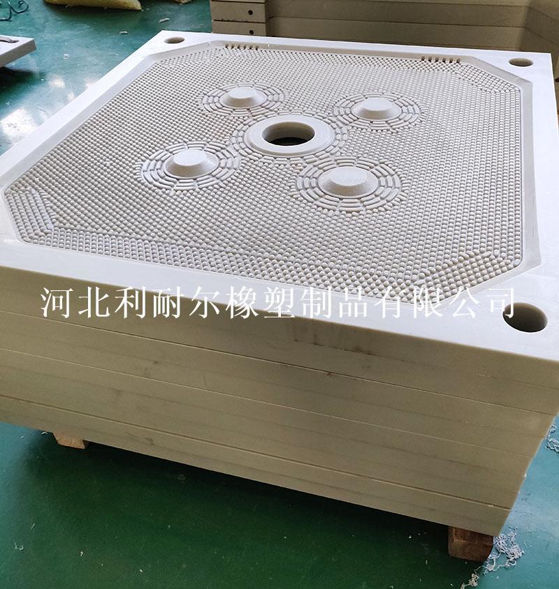
Each plate features a moulded cavity on both faces. When two plates are pressed together, their combined cavities form the filter chamber — no separate frame is needed. This mechanical filter press configuration is by far the most common in heavy industry today. It offers faster plate shifting, simpler maintenance, and compatibility with fully automatic operation including robotic cloth washing.
Membrane filter press (diaphragm press)
An evolution of the recessed chamber design where one or both plate faces incorporate a flexible rubber or elastomer membrane. After initial cake formation, the membrane is inflated to squeeze the cake mechanically — achieving residual moisture levels that pumping pressure alone cannot reach. In mineral concentrate dewatering, this can mean the difference between a cake at 14% and one at 9% moisture — a significant saving in transport and smelting energy costs.
Vertical plate pressure filter (VPA) and pressure plate filter (PF)
These designs enclose the entire filter stack within a pressure vessel, allowing filtration at pressure differentials of up to 10 bar across the cake — far higher than the hydraulic closing designs above. The BHS-type pressure plate filter, for instance, operates in a fully sealed environment and can integrate filtration, cake washing, and thermal or gas-flow drying in a single enclosed unit. These high-pressure filtration systems are preferred for fine particle applications — submicron pigments, pharmaceutical intermediates, catalysts — where conventional designs would require excessively long cycle times or produce unacceptably wet cakes.
| Type | Operating pressure | Typical cake moisture | Cycle time | Best suited for |
|---|---|---|---|---|
| Plate and frame | 4–8 bar | 25–40% | 45–90 min | Fine chemicals, small batch |
| Recessed chamber | 6–16 bar | 18–30% | 30–60 min | Mining, wastewater, general industry |
| Membrane / diaphragm | 8–16 bar feed + 6–16 bar squeeze | 9–20% | 25–50 min | Mineral concentrates, sludge dewatering |
| Vertical / PF (enclosed) | Up to 10 bar differential | 5–15% | 20–45 min | Fine particles, pharma, catalysts |
Key performance data: What numbers actually matter?
Engineers evaluating slurry dewatering equipment often focus on feed pressure and filter area. These are relevant — but incomplete. The following parameters collectively determine whether a plate pressure filter delivers its promised performance in practice.
Cake moisture and throughput
Residual cake moisture directly drives downstream transport and disposal costs. For mineral tailings destined for dry-stack storage — an increasingly common requirement under EU water recovery regulations — a target below 15–18% moisture is typical. Achieving this requires not just adequate feed pressure, but correct slurry conditioning (particle size distribution, pH, flocculant dosing) and appropriate filter cloth media selection. Throughput, expressed as tonnes of dry solids per square metre of filter area per hour, typically ranges from 15 to 120 kg/m²/h depending on cake compressibility and cycle time.
Energy consumption and total cost of ownership
An automatic filter press machine consumes energy through its feed pump, hydraulic closing system, membrane squeeze compressor (if fitted), and cloth washing system. A well-sized high-pressure filtration system consumes approximately 2–6 kWh per tonne of dry solids processed. This figure sounds modest, but at the throughput scales common in Finnish mining operations, the cumulative annual energy cost is substantial.
"Total cost of ownership analysis consistently shows that filter cloth replacement and energy account for 60–75% of lifetime operating costs in industrial filter press installations. Initial capital cost is rarely the dominant variable." — Based on published lifecycle cost benchmarks from European filtration industry studies, 2025.
When comparing offers, request the supplier's specific energy consumption figure (kWh/t dry solids) alongside cloth lifetime (number of cycles between replacement) and expected maintenance labour hours per year. These three numbers, combined with your local electricity price (the Finnish average industrial tariff was approximately €0.08–0.12/kWh in early 2026), allow a credible total cost of ownership calculation over a 15-year asset life.
How to select the right plate pressure filter for your process
Selection errors at the specification stage are expensive and difficult to reverse once equipment is installed. The methodology below reflects the approach used in professional engineering practice.
Bench-scale and pilot testing
No reputable supplier should size a full-scale industrial filter press based solely on theoretical calculations. The standard approach begins with a bench-scale leaf filter test using actual process slurry. This generates the specific cake resistance (α) and medium resistance (Rm) values that form the basis of sizing calculations. For projects above a threshold throughput — typically 5 t/h dry solids — a dedicated pilot trial using a compact test press is strongly recommended. Metso's Lappeenranta facility, for example, has conducted approximately 15,000 filtration trials since 1977, demonstrating that empirical testing remains irreplaceable for accurate scale-up.
Slurry characterisation and filterability
Four parameters dominate the selection outcome: solids concentration (% w/w), particle size distribution (d50 and d90), slurry temperature, and chemical compatibility with cloth and plate materials. A slurry with d50 below 10 µm is generally classified as difficult to filter and may require pre-treatment — flocculants, coagulants, or thermal conditioning — to reach acceptable cycle times. Slurries above 20% solids by weight typically form cakes quickly and suit high-throughput recessed chamber designs.
Filter cloth and plate material selection
Filter cloth media selection is one of the most consequential and least glamorous decisions in the entire specification process. The wrong cloth can halve effective capacity within weeks through blinding. For mineral processing applications, monofilament polypropylene weaves offer excellent cake release and chemical resistance. For fine particle or pharmaceutical applications, multifilament polyester or PTFE-coated cloths may be more appropriate. Plate materials range from standard polypropylene (suitable to approximately 90°C) through glass-fibre reinforced polymer to stainless steel for high-temperature or hygienic applications.
Maintenance, troubleshooting, and spare parts
Even the most capable automatic filter press machine will underperform — or fail entirely — without a structured maintenance programme. Reactive maintenance on pressure filtration equipment invariably costs more than scheduled prevention.
Routine maintenance intervals
Filter cloth replacement is typically the highest-frequency maintenance task. In continuous mining operations running three shifts, cloth lifetimes of 300–800 cycles are realistic depending on abrasivity, pH, and wash effectiveness. Beyond cloths, the hydraulic seal system on the closing cylinder requires inspection every 2,000–4,000 operating hours. Plate gaskets — which provide the inter-chamber seal in plate and frame filter press and recessed chamber designs — should be inspected quarterly and replaced at first signs of deformation or leakage, since a failed gasket allows slurry bypass and contaminates the filtrate stream.
Diagnosing common faults
Three failure modes account for the majority of unplanned downtime on a hydraulic press filter installation:
- Cloth blinding: Manifests as rising cycle pressure with declining filtrate flow. Root cause is usually inadequate cloth washing, chemically incompatible cloth material, or slurry pH outside the design range. Remedy: adjust wash sequence timing and inspect nozzle condition; consider cloth material change.
- Plate seal leakage: Visible slurry leakage between plates during the feed phase. Usually caused by worn gaskets, damaged plate faces, or insufficient hydraulic closing force. Check hydraulic pressure setting and inspect plate face condition at each cloth change.
- Incomplete cake discharge: Cake adhering to cloth rather than dropping freely. Common with sticky or fine-grained materials. Vibration-assist mechanisms, cloth surface treatment, or adjusted moisture targets may resolve this.
Spare parts strategy
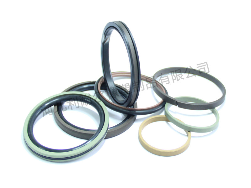
For Finnish and broader Nordic operations, geographic distance from manufacturing facilities in Central Europe or Asia makes on-site spare parts holding critical. A recommended minimum stock includes: one full set of filter cloths, two sets of plate gaskets, one hydraulic cylinder seal kit, one set of feed port manifold O-rings, and one complete cloth wash nozzle set. These components cover the failure modes responsible for over 85% of emergency stoppages in a typical mechanical filtration press installation.
Compliance and safety standards in 2026
Operating a plate pressure filter in the EU — including Finland — means navigating a framework of overlapping regulatory requirements. These are not optional formalities; non-compliance can result in operating restrictions, insurance voidance, or significant liability in the event of an incident.
CE marking and pressure equipment directive (PED)
Any plate pressure filter operating above 0.5 bar internal pressure and meeting the volume thresholds defined in EU Directive 2014/68/EU (Pressure Equipment Directive) must carry a CE mark and be accompanied by a Declaration of Conformity. For filter presses with hydraulic closing systems, the hydraulic circuit itself must also comply. Verify that the supplier provides the full technical file and that the CE marking references the correct PED category for your operating pressure range.
ATEX and explosion protection
If the slurry contains flammable solvents, or if the filter cake is a combustible dust once dry, the installation zone may be classified as a potentially explosive atmosphere under EU Directive 2014/34/EU (ATEX). In such cases, the entire filter press — including motors, sensors, and control panels — must be ATEX-rated for the appropriate zone classification. This requirement is frequently overlooked during the initial specification of wastewater treatment filter press installations handling solvent-contaminated sludges.
Environmental compliance and water recovery
The EU Critical Raw Materials Act and Finland's national water management regulations are both pushing toward higher water recovery rates in mineral processing. A correctly designed sludge dewatering filter integrated with a closed-loop filtrate return system can recover 90–98% of process water. Documenting this water balance is increasingly required as part of environmental permit applications for new and expanded mining installations in Finland. Of course, there are situations where full closed-loop recovery is not technically feasible — for instance, with high-salinity process waters — and in those cases partial recovery targets combined with appropriate effluent treatment represent the practical compliance pathway.
Frequently asked questions
Q: What is the difference between a plate pressure filter and a belt filter?
A: A plate pressure filter operates in batch cycles using sealed chambers and hydraulic pressure to achieve low residual cake moisture — typically 9–25%. A belt filter is a continuous device using gravity and mechanical compression, producing wetter cakes (20–40% moisture) but at higher continuous throughput. The choice depends on moisture targets, throughput, and process continuity requirements.
Q: How often should filter cloths be replaced on an industrial filter press?
A: Cloth lifetime depends on slurry abrasivity, chemical environment, and wash protocol. In mineral processing, 300–800 cycles per cloth set is typical. Performance indicators such as rising cycle times, increasing cake moisture, or visible cloth damage signal that replacement is due. Tracking cycle-by-cycle filtrate clarity is the most reliable early-warning method.
Q: Can a plate pressure filter handle highly abrasive mineral slurries?
A: Yes, but material selection is critical. Feed components in contact with abrasive slurry — manifolds, ports, and cloth — must be specified accordingly. High-chrome or ceramic-lined feed ports, robust monofilament polypropylene cloths, and reinforced plate faces extend service life significantly. Pilot testing with actual slurry remains the safest way to validate material choices before committing to full-scale equipment.
Q: What CE and regulatory certifications should a plate pressure filter have for use in Finland?
A: At minimum, the unit should carry CE marking under the Machinery Directive 2006/42/EC and, if operating above the PED thresholds, also under Directive 2014/68/EU. ATEX certification is required for installations in explosive atmosphere zones. Confirm that the supplier provides a full Declaration of Conformity and technical file in a language acceptable to Finnish authorities — Finnish or English is standard.
Q: How do I calculate total cost of ownership for a plate pressure filter?
A: Start with capital cost, then add annual energy cost (kWh/t × throughput × electricity tariff), annual cloth and gasket replacement cost, maintenance labour, and any chemical conditioning costs. Divide the 15-year total by cumulative tonnes processed to get a cost-per-tonne figure. This metric is the most useful basis for comparing a plate pressure filter against belt filter or centrifuge alternatives.
In summary, the plate pressure filter remains one of the most versatile and effective tools in industrial solid-liquid separation, particularly in demanding Nordic mining and processing environments. Selecting the right type, sizing it correctly through empirical testing, and operating it within a structured maintenance and compliance framework are the three factors that determine whether the investment delivers its intended return. With the 2026 push toward dry-stack tailings, water recovery, and energy efficiency, the technology continues to evolve — and the gap between a well-specified installation and a poorly specified one is wider than ever.
Related News



Get a Quote